Sign in to save

Bookmark this page so you can find it later.

Sign in to save

Bookmark this page so you can find it later.

Computer Science high-school May 24, 2026

How Does a Computer Add Two Numbers?

From bits to a working adder
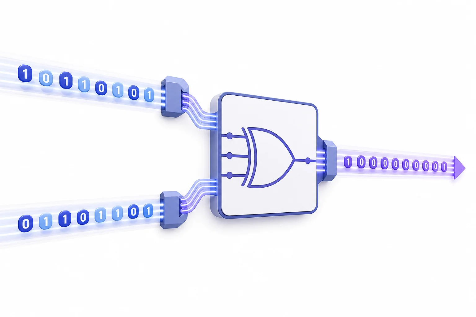
Educational diagram showing two binary numbers entering a simple computer circuit and producing a binary sum.

Computers store numbers as patterns of 0s and 1s. Tiny switches combine those patterns one place at a time. Each place makes an answer digit and sometimes passes a carry to the next place.

Big Idea. CSTA 3A-CS-02 connects binary addition to how hardware uses layers of abstraction to carry out computation.

A computer does not add the way a person does on paper, but the idea is close. It lines up numbers by place value, adds the rightmost place first, and carries when a place gets too large. The difference is that a computer uses only two symbols, 0 and 1. That makes every number a binary number inside the machine. The number 13, for example, can be stored as $1101_2$. Each digit is called a bit. A circuit adds bits using logic gates. These gates follow simple rules from Boolean logic, where every input is either off or on. A helpful review is the Binary cheat sheet or the Boolean Logic cheat sheet. When many tiny adders are chained together, a computer can add large numbers in a few steps.

Why 0s and 1s work
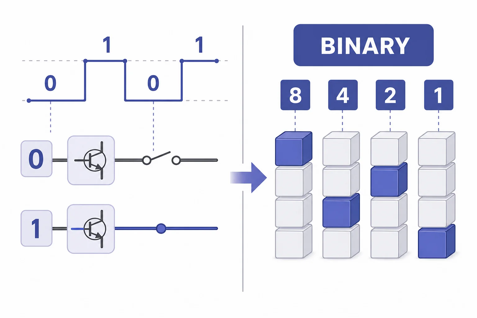
Diagram comparing decimal place values with binary place values and showing voltage levels mapped to 0 and 1.
Binary uses two stable states and powers of two.
A computer is built from electronic parts that are easiest to control in two clear states. A wire can carry a low voltage or a high voltage. A transistor can mostly block current or let it pass. Engineers match those physical states to the symbols 0 and 1. This choice is useful because small noise in the signal does not usually change the meaning. A slightly weak high signal can still count as 1. A slightly raised low signal can still count as 0. Binary also fits place value. In decimal, each place is worth ten times the place to its right. In binary, each place is worth two times the place to its right. So $1011_2$ means 8 plus 0 plus 2 plus 1, which equals 11 in decimal.

Binary is a place-value system with only two digits.

Logic gates are rules in hardware
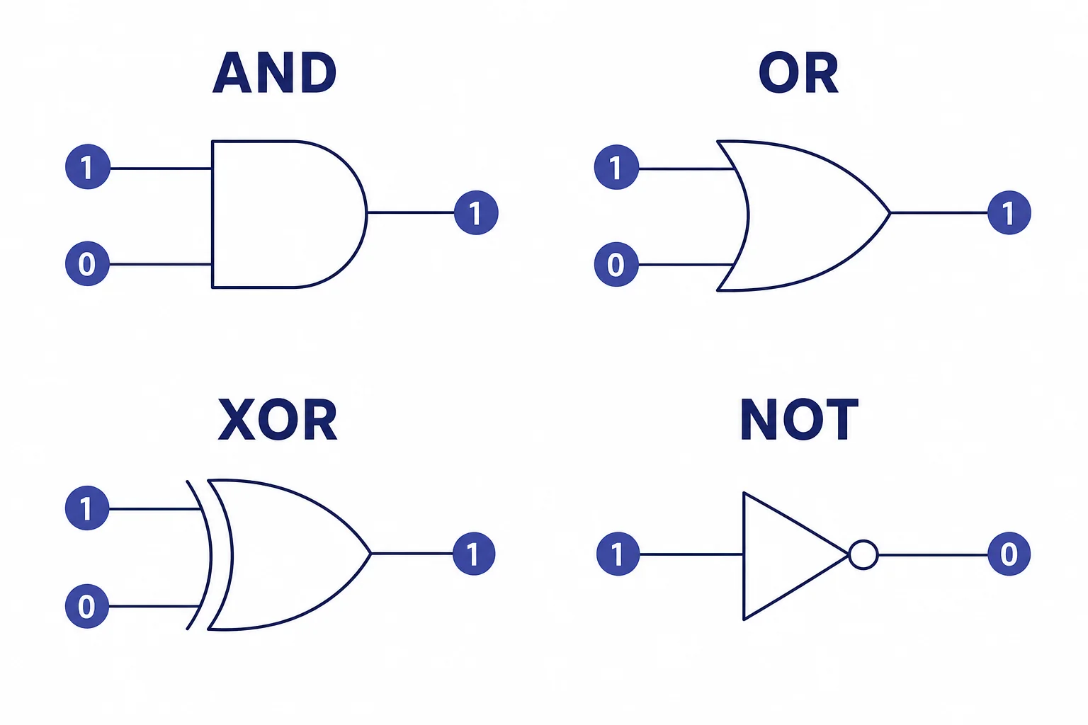
Four basic logic gates shown with two binary inputs and one binary output for each gate.
Gates turn Boolean rules into circuit behavior.
A logic gate is a small circuit with one or more inputs and one output. Each input is treated as 0 or 1. The output follows a rule. An AND gate outputs 1 only when both inputs are 1. An OR gate outputs 1 when at least one input is 1. A NOT gate flips a value. The XOR gate is especially important for addition. It outputs 1 when the two inputs are different. That matches one part of adding a single binary place. If you add 0 and 1, the result bit is 1. If you add 1 and 0, the result bit is also 1. If you add 0 and 0 or 1 and 1, the result bit is 0. Gates make these rules happen with electricity instead of pencil marks.

A gate is a physical device that follows a Boolean rule.

The half-adder
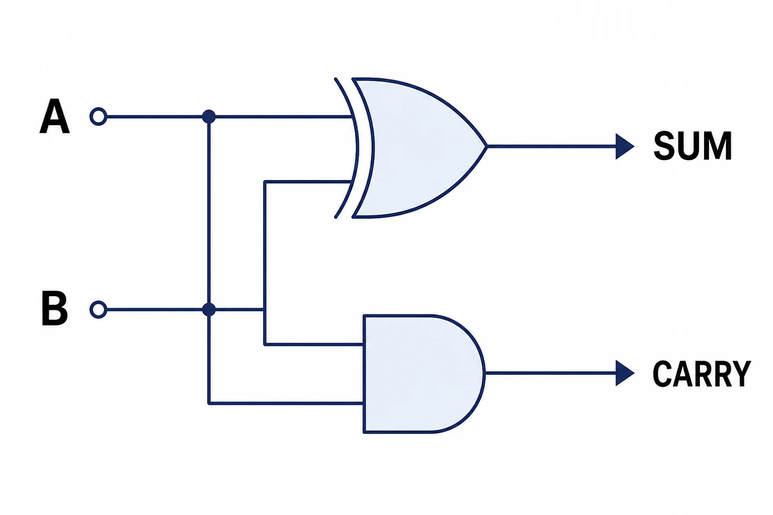
Half-adder schematic showing inputs A and B feeding XOR and AND gates to produce sum and carry outputs.
A half-adder makes a sum bit and a carry bit.
A half-adder adds two bits. It has two inputs, often called A and B. It has two outputs. One output is the sum bit. The other output is the carry bit. The sum bit comes from an XOR gate because the sum is 1 only when A and B are different. The carry bit comes from an AND gate because a carry happens only when A and B are both 1. Try the four cases. 0 plus 0 gives sum 0 and carry 0. 0 plus 1 gives sum 1 and carry 0. 1 plus 0 gives sum 1 and carry 0. 1 plus 1 gives sum 0 and carry 1, which means two in binary. A half-adder can handle the first column of a binary addition problem, but it cannot accept a carry from an earlier column.

XOR finds the sum bit, and AND finds the carry bit.

The full-adder
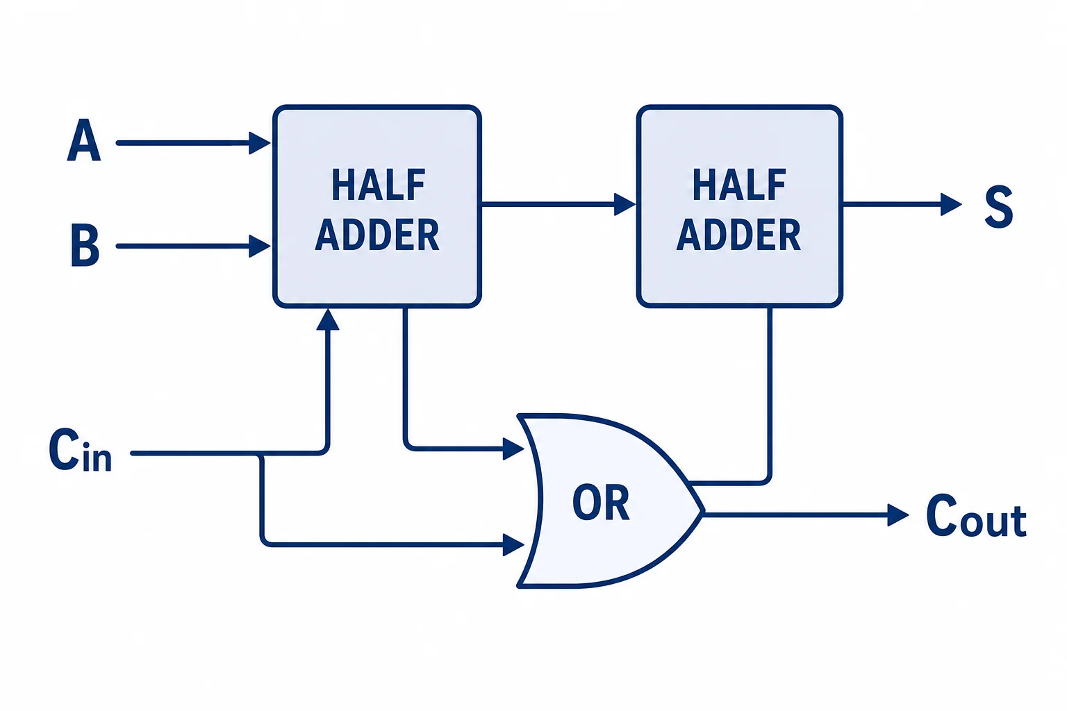
Full-adder schematic made from two half-adders and an OR gate with carry in and carry out.
A full-adder accepts a carry in and sends a carry out.
Most columns in binary addition need one more input. That input is the carry from the column on the right. A full-adder adds three one-bit values. The inputs are A, B, and carry in. The outputs are sum and carry out. One way to build it is to connect two half-adders and an OR gate. The first half-adder adds A and B. The second half-adder adds that result to carry in. The two carry signals are then joined by an OR gate. If either part creates a carry, the full-adder sends a carry out to the next column. This is how a computer handles the same carrying rule used in hand addition. The design is still made from simple gates, but the pieces are arranged so carries can move across the number.

A full-adder is the basic building block for multi-bit addition.

Chaining adders together
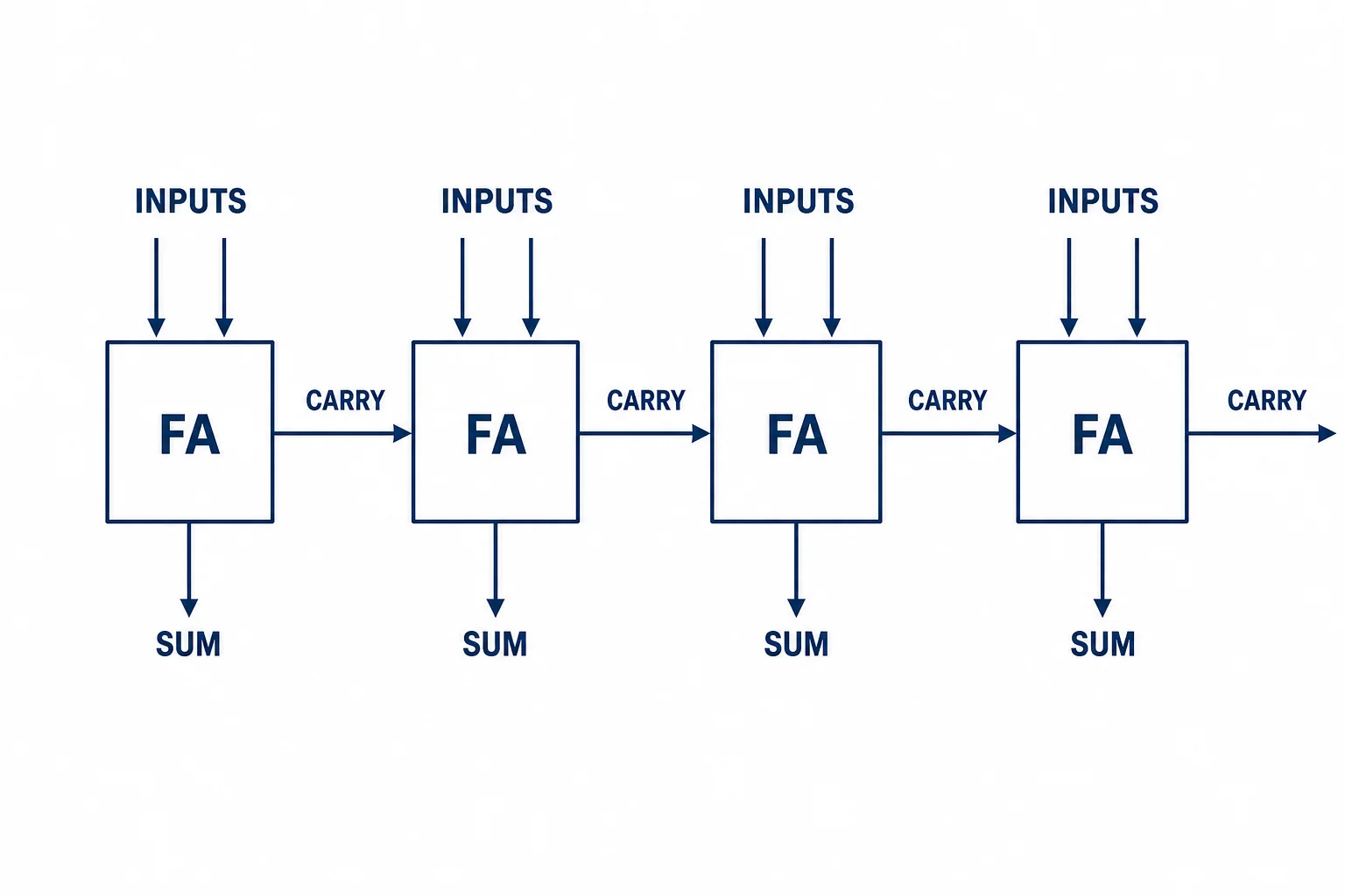
Four full-adders chained together to add two 4-bit binary numbers with carry moving between bit positions.
Multi-bit addition comes from repeated full-adders.
To add larger binary numbers, a computer places several full-adders side by side. Each adder handles one bit position. The rightmost adder starts with a carry in of 0. Its carry out becomes the carry in for the next adder. This repeats across the number from right to left. For example, adding $0101_2$ and $0011_2$ produces $1000_2$. That is 5 plus 3 equals 8. A simple chain like this is called a ripple-carry adder because each carry ripples to the next place. Real processors use faster designs for many jobs, but the core idea remains the same. Binary numbers are represented by bits, gates combine the bits, and adders organize the gates so the circuit follows arithmetic rules.

Large additions are built from many small one-bit additions.

Vocabulary

bit
A single binary digit, either 0 or 1.
binary
A base-two number system that uses powers of two for place value.
logic gate
A circuit part that takes binary inputs and produces a binary output by following a rule.
XOR
A logic rule that outputs 1 when its two inputs are different.
carry
A value passed to the next place when a column adds up to two or more.
full-adder
A circuit that adds two input bits plus a carry in, then produces a sum bit and a carry out.

In the Classroom

Build a truth table

20 minutes | Grades 9-12

Students list all input pairs for A and B, then fill in the outputs for XOR and AND. They use those results to explain why the two gates form a half-adder.

Act out a ripple-carry adder

25 minutes | Grades 9-12

Give each student group one bit position in a binary addition problem. Each group computes its sum bit, then passes a carry card to the next group if needed.

Trace a full-adder schematic

30 minutes | Grades 10-12

Students follow the path of A, B, and carry in through two half-adders and an OR gate. They test several input cases and check that the final sum and carry out match binary addition.

Key Takeaways

  • Computers represent numbers with bits, which are 0s and 1s.
  • Binary uses powers of two for place value.
  • Logic gates turn simple Boolean rules into electrical behavior.
  • A half-adder adds two bits using XOR for the sum and AND for the carry.
  • A full-adder includes a carry in, so many adders can be chained for larger numbers.