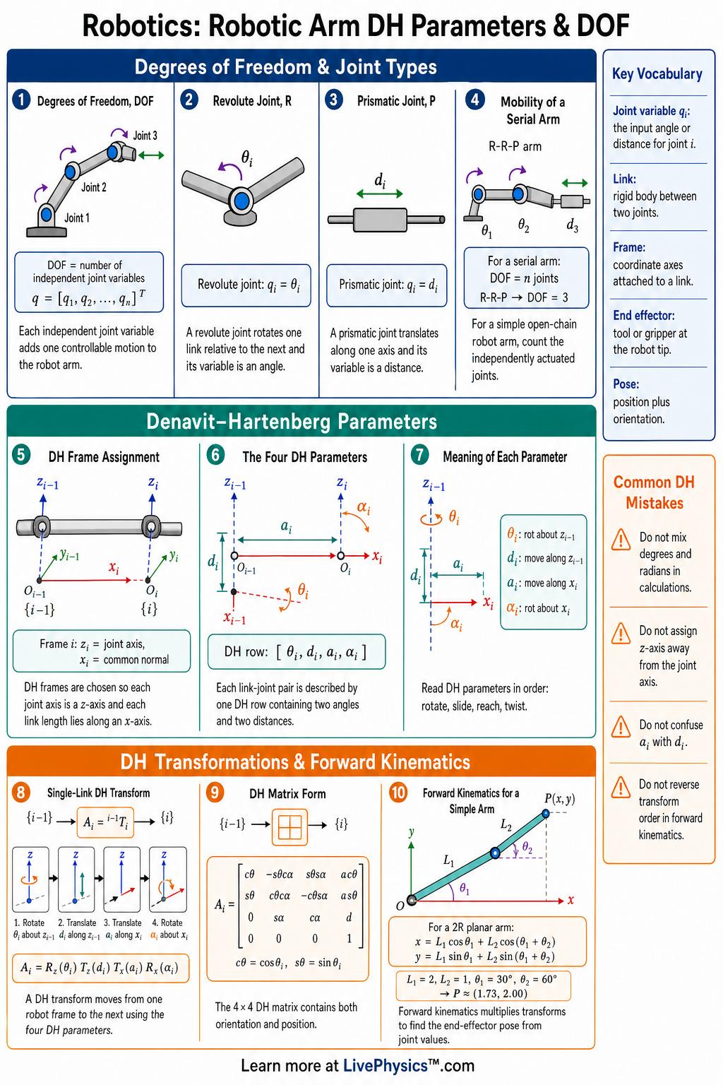
Robotic arm motion is described by joints, links, coordinate frames, and degrees of freedom. This cheat sheet helps students organize the geometry of a manipulator so they can model where the end effector moves. DH parameters give a standard way to turn a physical arm into a table of numbers and transformations.
Understanding DOF helps predict what tasks a robot can perform and what motions may be impossible.
The core idea is to attach a coordinate frame to each link, then describe the motion from one frame to the next using four DH parameters. Each link transform combines rotation and translation into one 4 by 4 homogeneous transformation matrix. Multiplying these matrices gives forward kinematics, which maps joint variables to end effector position and orientation.
The number and type of joints determine the robot's degrees of freedom and workspace.
Key Facts
- Degrees of freedom, or DOF, is the number of independent joint variables needed to describe a robot arm's configuration.
- A revolute joint contributes one angular variable, usually theta, and a prismatic joint contributes one linear variable, usually d.
- The four standard DH parameters are theta, d, a, and alpha for each link-to-link frame transformation.
- In standard DH convention, theta is the rotation about z(i-1), d is the translation along z(i-1), a is the translation along x(i), and alpha is the rotation about x(i).
- A homogeneous transform has the form T = [R p; 0 0 0 1], where R is a 3 by 3 rotation matrix and p is a 3 by 1 position vector.
- Forward kinematics is found by multiplying transforms in order, T0n = T01 T12 T23 ... T(n-1)n.
- For a revolute joint, theta is variable and d, a, and alpha are usually constant; for a prismatic joint, d is variable and theta, a, and alpha are usually constant.
- The end effector pose includes both position and orientation, so a general 3D pose requires up to 6 DOF.
Vocabulary
- Degree of freedom
- A degree of freedom is one independent motion variable that changes the configuration of a robot.
- DH parameters
- DH parameters are four values, theta, d, a, and alpha, used to describe the transform between neighboring robot link frames.
- Revolute joint
- A revolute joint is a rotating joint whose joint variable is an angle.
- Prismatic joint
- A prismatic joint is a sliding joint whose joint variable is a distance.
- Homogeneous transformation
- A homogeneous transformation is a 4 by 4 matrix that represents rotation and translation in one coordinate-frame change.
- Forward kinematics
- Forward kinematics calculates the end effector position and orientation from known joint variables and link dimensions.
Common Mistakes to Avoid
- Confusing DOF with the number of links is wrong because DOF depends on independent joint variables, not simply on how many rigid parts the arm has.
- Assigning DH axes inconsistently is wrong because each transform depends on the chosen z and x axes, so inconsistent frames produce incorrect kinematics.
- Using degrees inside calculator functions set to radians is wrong because sin(theta) and cos(theta) must use the angle unit expected by the tool.
- Multiplying transformation matrices in the wrong order is wrong because matrix multiplication is not commutative, so T01 T12 gives a different result from T12 T01.
- Treating theta as variable for every joint is wrong because prismatic joints usually vary d while theta stays constant.
Practice Questions
- 1 A robot arm has 4 revolute joints and 2 prismatic joints. How many degrees of freedom does it have?
- 2 For a revolute joint with theta = 90 degrees, d = 0.20 m, a = 0.35 m, and alpha = 0 degrees, which DH parameter is the joint variable?
- 3 A planar arm has two revolute joints with link lengths L1 = 0.40 m and L2 = 0.30 m. If both joint angles are 0 degrees and the links point in the same direction, what is the end effector distance from the base?
- 4 Why does a 6 DOF robotic arm usually have more ability to position and orient a tool in 3D space than a 3 DOF arm?
Understanding Robotic Arm DH Parameters & DOF
A consistent frame assignment matters more than memorizing a table. Start by finding each joint axis, since this is the axis about which a rotary joint turns or along which a sliding joint moves. Place the frame origin at a useful point on that axis, usually where two axes meet or where their shortest separation begins.
Choose each x direction along the common normal between neighboring joint axes. Parallel axes need extra care because there may be many possible common normals.
Any sensible choice can work, but changing choices halfway through a model creates incorrect results. Draw every frame clearly before filling in numbers.
The transform for one link describes a sequence of motions in a fixed order. Order matters because turning first then moving usually ends at a different place from moving first then turning. The rotation part tells how the new frame is pointed relative to the old frame.
The position part tells where its origin is located. The final row of a homogeneous transform makes rotations and translations work together in one calculation.
When transforms are multiplied from the base toward the tool, each later motion is interpreted in the coordinate system created by earlier motions. This is why matrix multiplication in robotics cannot usually be rearranged.
Degrees of freedom should be connected to the job the arm must perform. A tool moving freely in space may need three independent shifts and three independent turns. An arm with fewer available motions can still do useful work.
A welding torch following a flat seam may need only a limited set of orientations. A camera mount may need position control with one viewing direction. An arm with more joints than a task requires is called redundant.
Redundancy can help it avoid obstacles or keep away from joint limits. It can also make control harder because several joint configurations may place the tool at the same pose.
Real robot models must include limits and physical offsets. A joint may be able to rotate in theory but be stopped by cables, a housing, or another link. These restrictions shrink the reachable workspace.
Certain arm shapes produce singularities, where a small desired tool motion would require very large joint motion or where one direction of motion is lost. A stretched elbow is a common example. When checking a forward kinematics model, use simple test poses first.
Set rotary angles to zero when possible, then verify each link length and direction against a sketch. Keep all distances in one unit, such as metres or millimetres, and keep angle units consistent. Finally, include the tool length, since the useful point is often at a gripper tip rather than at the final wrist joint.