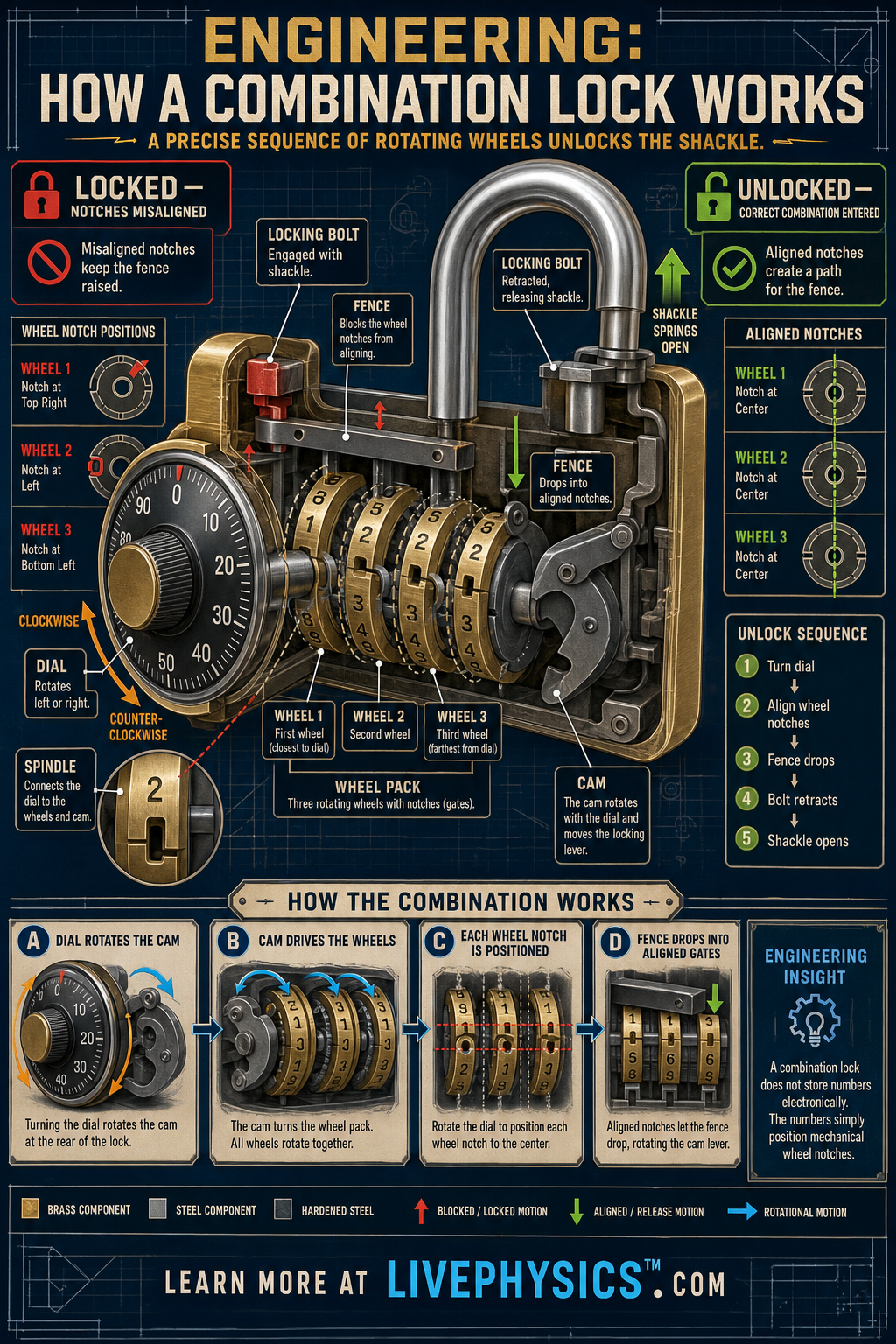
A rotary combination lock uses a carefully timed sequence of dial turns to control hidden wheels inside the lock body. Each wheel contains a small gap called a gate or notch, and the lock opens only when every gate reaches the same position. This design turns a memorized number sequence into a mechanical security system without requiring a key.
Understanding the mechanism connects rotational motion, precise alignment, and force transfer in a compact machine.
Turning the dial rotates a spindle and cam at the center of the lock. Drive pins on the wheel assembly pick up one wheel at a time, so changing direction and passing numbers a specified number of times positions different wheels independently. When the correct combination aligns all wheel gates, a fence can drop into the aligned spaces.
The cam then moves the locking bolt away from the shackle, allowing the shackle to spring open.
Understanding Engineering, How a Combination Lock Works
Inside the case, the moving parts must be made with very small clearances. A wheel needs to turn freely on the spindle, yet it cannot wobble much from side to side. Too much looseness makes the stopping position uncertain.
Too little clearance creates friction and can make the dial feel rough. The fence has the same design problem.
It must be narrow enough to detect a correctly placed gate, but it needs enough room to move without jamming. Engineers choose materials, surface finishes, and spring strength so the lock still works after years of dust, moisture, and repeated use.
The starting turns in a combination procedure have an important mechanical job. They bring all the internal wheels into contact with the driving part before a specific wheel is set. Each connection has a small amount of free movement called slack.
A change in direction uses that slack to leave some wheels behind while another wheel is moved. This is why the number of passes matters.
Missing one pass can leave a wheel one full rotation away from its intended setting, even if the visible number seems correct. Different lock models may use different procedures because the locations and shapes of their driving tabs are not identical.
A lock gains security because its internal settings are hidden from view. If a dial has forty possible positions and three independent wheels, the wheel pack can represent up to forty times forty times forty possible arrangements. The real number may be lower when a maker limits usable settings, but it is still large enough to prevent casual guessing.
Some better locks include false gates. These are shallow grooves that can make the fence move a little at an incorrect setting. They reduce clues that a person might feel through the dial.
This shows that security engineering is not only about adding more parts. It is about controlling the information that escapes through sound, motion, and resistance.
Students meet similar mechanisms in door latches, safe handles, rotary switches, and machines with adjustable settings. In each case, rotational motion must be turned into a controlled linear movement. The cam is especially useful because its curved edge changes the distance from its center as it rotates.
That changing distance pushes a lever or bolt at a chosen point in the turn. When studying a lock diagram, trace the path of force from your fingers to the dial, spindle, wheels, fence, lever, and bolt.
Notice which parts rotate, which parts slide, and which parts are held by springs. This method makes a complicated mechanism easier to understand as a chain of simple motions.
Key Facts
- The dial is attached to a spindle, so turning the dial rotates the central cam.
- A wheel pack commonly contains 3 wheels, and each wheel has one gate or notch.
- Drive pins transfer rotation from one wheel to the next after dial slack is taken up.
- The combination sequence uses direction changes to set separate wheel positions.
- The lock opens only when all wheel gates align beneath the fence.
- For a dial with N equally spaced positions, one dial division corresponds to θ = 360°/N.
Vocabulary
- Dial
- The numbered rotating control that the user turns to enter a combination.
- Spindle
- The central shaft that carries rotational motion from the dial into the lock.
- Wheel
- A rotating disk inside the lock that has a gate positioned by the combination.
- Gate
- A notch in a wheel that must align with the other wheel gates for the lock to open.
- Fence
- A metal bar that drops into aligned wheel gates and permits the locking mechanism to release.
Common Mistakes to Avoid
- Treating every dial number as a direct position for every wheel is wrong because the wheels are picked up sequentially through drive pins and dial direction changes.
- Assuming one aligned notch is enough to open the lock is wrong because the fence must enter the gates of every wheel in the stack.
- Forgetting the specified number of passes over a combination number is wrong because extra turns are used to engage and position the deeper wheels.
- Pulling hard on the shackle while entering the combination is wrong because tension can bind the bolt or fence and prevent smooth movement of the internal parts.
Practice Questions
- 1 A combination-lock dial has 40 equally spaced positions. What angle, in degrees, does the dial rotate when it moves from one number to the next?
- 2 A student turns a 40-position dial clockwise from 0 to 28. Assuming the dial numbers increase clockwise, through what angular displacement has the dial rotated?
- 3 Explain why a combination lock requires the gates on all of its wheels to align before the shackle can be released.