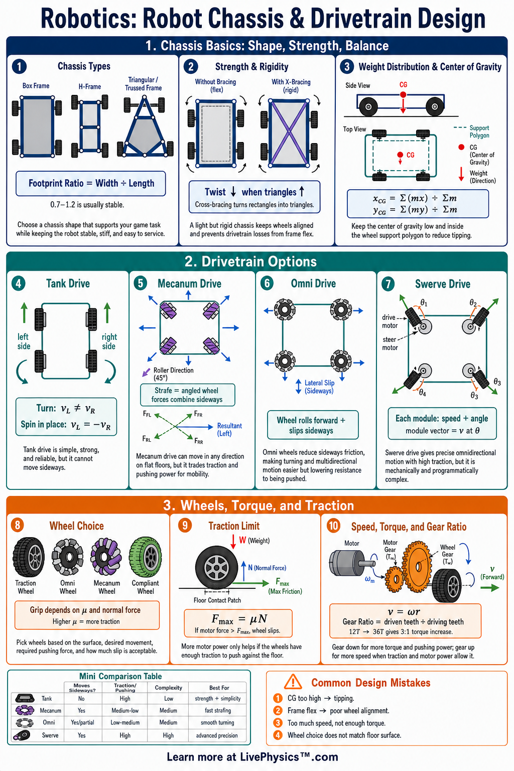
Robot chassis and drivetrain design covers the frame, wheels, motors, gears, and layout that let a robot move reliably. Students need this cheat sheet to connect mechanical choices to speed, pushing force, turning ability, and balance. A strong drivetrain helps a robot drive straight, climb obstacles, protect components, and perform tasks consistently.
Good design starts with clear requirements, such as floor type, payload, turning space, and competition rules.
The most important ideas are motor torque, gear ratio, wheel size, traction, center of mass, and chassis stiffness. Gear reductions trade speed for torque, while larger wheels usually increase speed but reduce pushing force for the same motor torque. Traction depends on normal force and the coefficient of friction, and it limits how much force the drivetrain can apply before slipping.
Stability improves when the center of mass is low, the wheelbase is wide enough, and the frame resists bending.
Key Facts
- Gear ratio = driven gear teeth ÷ driving gear teeth, and a larger gear ratio increases output torque while decreasing output speed.
- Output torque = motor torque × gear ratio × drivetrain efficiency, where efficiency is usually less than 1 because of friction losses.
- Output speed = motor speed ÷ gear ratio, so a 5:1 reduction makes the wheel turn one fifth as fast as the motor.
- Wheel linear speed = wheel circumference × wheel revolutions per second, and wheel circumference = pi × wheel diameter.
- Available traction force = coefficient of friction × normal force, so a robot slips when drive force is greater than available traction.
- Pushing force at the wheel is approximately wheel torque ÷ wheel radius, so smaller wheels can increase pushing force for the same torque.
- Turning radius depends on drivetrain type, wheel spacing, and wheel control, with tank drive and mecanum drive able to turn in place.
- A lower center of mass and wider support base increase stability and reduce the chance of tipping during turns, acceleration, or collisions.
Vocabulary
- Chassis
- The main structural frame of a robot that supports motors, wheels, electronics, mechanisms, and loads.
- Drivetrain
- The system of motors, gears, belts, chains, axles, and wheels that moves the robot.
- Gear ratio
- The ratio comparing input rotation to output rotation, often used to trade speed for torque or torque for speed.
- Torque
- A turning force that causes rotation, commonly measured in newton-meters or pound-inches.
- Traction
- The grip between the wheel and the ground that allows the robot to accelerate, turn, or push without slipping.
- Center of mass
- The average location of an object's mass, which strongly affects balance and tipping risk.
Common Mistakes to Avoid
- Choosing the fastest gear ratio without checking torque is wrong because the robot may stall, accelerate slowly, or fail to climb obstacles.
- Ignoring wheel diameter is wrong because larger wheels change both speed and pushing force even when the motor and gear ratio stay the same.
- Assuming more motor power always means more pushing force is wrong because traction limits the maximum force before the wheels slip.
- Mounting heavy parts high on the chassis is wrong because it raises the center of mass and makes tipping more likely during turns or impacts.
- Building a flexible frame is wrong because bending can misalign wheels, waste power, damage components, and make the robot drive unpredictably.
Practice Questions
- 1 A motor spins at 6000 rpm and drives a wheel through a 6:1 gear reduction. What is the wheel speed in rpm?
- 2 A drivetrain has a motor torque of 0.40 N·m, a 5:1 gear ratio, and 80% efficiency. What is the output torque?
- 3 A robot wheel has a diameter of 10 cm and spins at 4 revolutions per second. Using pi = 3.14, what is the robot's approximate linear speed in cm/s?
- 4 A robot needs to push heavy game pieces on carpet but also turn accurately in a small space. Explain two drivetrain or chassis design choices that would help.
Understanding Robot Chassis & Drivetrain Design
A motor does not provide the same turning force at every speed. It produces its greatest torque when it is stalled, meaning the shaft is not turning. At that point it draws a very large current and turns electrical energy into heat.
A robot should not be designed to operate near stall for long. The useful working region is usually somewhere between zero speed and the motor's free speed. This is why a drivetrain that seems powerful on paper can still overheat, drain its battery, or trip a circuit breaker.
Designers estimate the robot mass, desired acceleration, slope, and expected contact forces. They then choose a reduction that lets the motors work without spending most of a match near their limit.
Acceleration changes how weight is shared among the wheels. When a robot accelerates forward, some load shifts toward the rear. When it brakes, load shifts toward the front.
The wheels carrying more load can usually grip better, while lightly loaded wheels may spin or lose steering control. This effect matters especially for tall robots and robots with a short distance between front and rear wheels. Battery location, arm position, and carried objects can move the center of mass during operation.
A robot that is stable while empty may tip once it lifts a game piece. Students should test the robot with its heaviest expected load, not only on a workbench.
Wheel arrangement changes more than turning style. A two wheel drive robot often has passive wheels or skids to support the other end. It can be simple and light, but the passive supports may create drag or catch on uneven surfaces.
Four wheel drive spreads the load and improves grip, yet fixed wheels can resist sideways motion during a turn. This resistance is called scrub. A long four wheel drive chassis may turn poorly on high grip carpet because every wheel is trying to follow a slightly different path.
Designers reduce scrub with a shorter wheelbase, a dropped center wheel, different wheel types, or a drivetrain that controls each side independently. Mecanum wheels permit sideways movement, but their angled rollers waste some force and can make precise driving harder on uneven floors.
The chassis must keep motor shafts, gearboxes, and wheels in the positions assumed by the design. Even a small frame bend can misalign gears, tighten a chain, loosen a belt, or make one wheel carry less weight. Misalignment creates friction, noise, and inconsistent motion.
Good frames use cross braces and secure bearing mounts, while still leaving room to reach fasteners and replace parts. Chains and belts need correct tension. Too loose can cause skipping, while too tight overloads bearings and motors.
During testing, students should observe wheel slip, current draw, motor temperature, turning behavior, and whether the robot drives differently in each direction. These clues reveal mechanical problems before they become failures during a run.