Understanding Gear Train Calculator
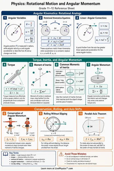
A gear works because the teeth prevent the two wheels from sliding past each other at their contact point. Each tooth pushes the next tooth, so the rims move through the same distance while the wheels turn through different angles.
The number of teeth determines the turning ratio. For one gear pair, output speed equals input speed times the number of teeth on the driver divided by the number of teeth on the driven gear. A larger driven gear therefore makes fewer turns for each turn of the driver.
Two external gears rotate in opposite directions. Adding another external gear reverses the direction again, so the first and last gears can rotate in the same direction. Direction matters in machines where a shaft must turn a fan, wheel, or conveyor correctly.
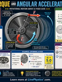
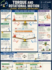
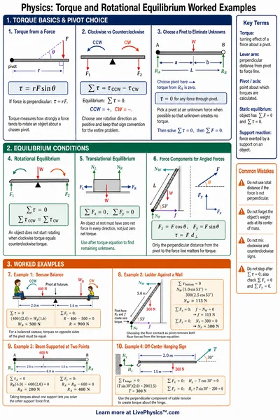
Gears trade rotational speed for turning effect, called torque. In an ideal pair, reducing speed by a factor of three increases output torque by a factor of three. This follows conservation of energy, since torque times angular turning distance must balance between input and output.
Real gear systems lose some energy through friction, sound, vibration, and heating. Bearings and tooth surfaces create much of this loss. Lubrication reduces wear and friction, though no real gearbox delivers exactly the ideal calculated torque.
A compound train has at least one shaft carrying two gears fixed together. Both gears on that shaft have the same rotational speed, even when they have different diameters. Each meshing pair contributes its own ratio, and the overall ratio comes from multiplying those ratios.
Small gears between the main driver and driven gear are often called idler gears. An idler changes the direction arrangement or spacing between shafts, but it does not change the size of the overall ratio when considered by itself. This is useful when machine parts cannot be placed close together.
Planetary systems place several gears around a central sun gear inside a ring gear with internal teeth. The planet gears can spin on their own shafts while their carrier moves around the sun. This layout fits a large ratio into a compact space.
The result from a planetary system depends on which member is held still, which member receives input, and which member provides output. Holding the ring gives a different result from holding the sun. This is why automatic transmissions can provide several gear ratios using one planetary set.
Gear teeth must have matching shape and spacing to mesh smoothly. Engineers use a standard tooth size, often described by module or pitch, so compatible gears have teeth of the same size. A correct ratio alone is not enough if the teeth cannot physically fit together.
Backlash is the small gap between mating teeth. Some clearance is needed for lubrication and thermal expansion, but too much creates rattling and inaccurate motion. Clock mechanisms, robots, and 3D printers need low backlash when precise positioning matters.
When studying gear calculations, track three things separately, speed, direction, and torque. Check whether gears share a shaft or actually mesh, because those connections behave differently. Units such as revolutions per minute and newton metres help prevent mistakes when comparing a calculated result with a real machine.