Understanding Block and Tackle System Calculator
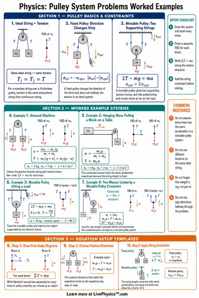
A block and tackle changes the direction and size of the force needed to lift a load. It does this by spreading the load across several rope sections, called supporting strands. Each strand pulls upward on the moving block with nearly the same tension in an ideal system.
With one supporting strand, the applied pull must be about as large as the load weight. With four supporting strands, each strand can carry roughly one quarter of that weight. The ideal mechanical advantage is therefore the number of rope sections that directly support the lower block.
This easier pull has a cost. To raise the load one metre, the free end of the rope must move a distance equal to the number of supporting strands times one metre. Work is conserved in an ideal machine, so less force requires more pulling distance.
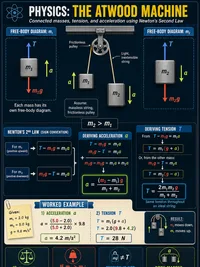
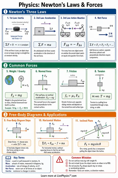
Rope tension is the pulling force carried through a taut rope. In textbook problems, a massless rope over frictionless pulleys has equal tension everywhere. Real ropes and pulleys do not meet these conditions, which is why the actual effort is larger than the ideal prediction.
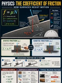
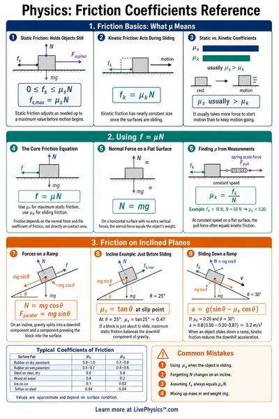
Friction appears at pulley axles, inside bearings, and where the rope bends around each sheave. A sheave is the grooved wheel inside a pulley block. Every contact removes a small amount of useful energy, mostly by turning it into heat.
These losses build up through the system. Adding pulleys may increase the ideal advantage, yet it can reduce efficiency if the rope passes around many stiff or dirty sheaves. This explains why a large rig does not always feel as easy as its strand count suggests.
The rope anchor matters because it determines where the first rope section begins and how forces enter the blocks. When the anchor is on the fixed upper block, it transfers part of the load to the support above. When it is on the moving lower block, the lower block receives that rope force directly.
Following the rope path carefully prevents common counting mistakes. Count only strands that lift the lower block, not the free end being pulled unless it actually supports that block. A strand that merely changes the pull direction can be useful, but it does not automatically add lifting advantage.
Fixed pulleys are often included to make the worker pull downward rather than upward. Pulling downward lets a person use body weight and maintain a safer stance. This direction change may improve control without changing the ideal mechanical advantage.
Construction hoists, sailing rigs, theatre fly systems, rescue equipment, and old workshop cranes use related ideas. In each case, the designer balances lifting force, rope travel, speed, available space, and safety. A system suited to slowly raise a heavy stage set may be unsuitable for a fast rescue.
Real lifting systems need a safety margin because ropes, hooks, and pulleys have maximum working loads. Uneven loading, worn grooves, crossed rope sections, or sudden jerks can raise forces beyond a simple static calculation. People should never stand under a suspended load or place hands near running rope.
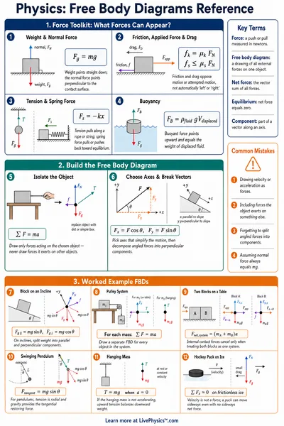
When studying a diagram, identify the fixed block, moving block, rope anchor, and free end before doing any calculation. Then trace every rope section in order and mark the ones supporting the load. Finally compare ideal force with real force to see how friction changes the result.