Polarization & Malus's Law Lab
Rotate two or three linear polarizers, watch the beam attenuate, and measure the transmitted intensity against the prediction I = I_0 cos^2(theta). Compare unpolarized and polarized sources, explore the three-polarizer paradox, and step through sunglasses and LCD pixel scenarios.
Guided ExperimentMalus's Law Investigation
If you rotate the second polarizer from 0 to 90 deg relative to the first, what do you predict will happen to the transmitted intensity?
Write your hypothesis in the Lab Report panel, then click Next.
Polarizer Stack
Tick marks on each polarizer show its transmission axis. Single-line marks on the beam show the polarization direction after each stage; crossed marks before the first polarizer indicate unpolarized light.
Controls
Results
- Source100.000 W/m^2 (unpolarized)
- After polarizer 150.000 W/m^2
- After polarizer 237.500 W/m^2
Malus's law curve
Red dot tracks the current angle between the analyzer and its incoming polarization axis. Yellow dots are recorded data points. The curve plots the theoretical Malus's law I / I_first = cos^2(theta).
Input I_0 = 100.0 W/m^2. After first polarizer = 50.00 W/m^2 (used as I_first on the y-axis ratio above).
Data Table
(0 rows)| # | Trial | Polarizer 1(deg) | Polarizer 2(deg) | Angle between(deg) | I_0 input(W/m^2) | I transmitted(W/m^2) | I / I_0 | cos^2(theta) |
|---|
Reference Guide
Malus's Law
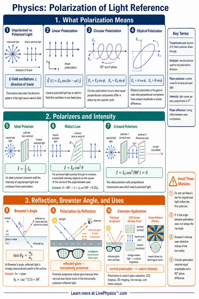
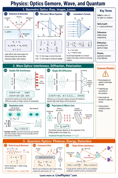
When polarized light hits a linear polarizer, only the component of the electric field aligned with the polarizer's transmission axis passes through. The intensity is reduced by the cosine squared of the angle between them.
At theta = 0 the two axes are aligned and all light passes. At theta = 90 deg they are perpendicular and the beam is blocked. At theta = 45 deg exactly half the intensity gets through.
Unpolarized Input
Natural light (sun, incandescent bulbs) is a random mixture of polarization directions. A single polarizer cuts the intensity in half no matter how it is oriented, because exactly half of the random orientations project onto its axis.
After this first polarizer, the light is fully polarized along the polarizer's axis, and Malus's law applies to every later polarizer in the stack.
Three-Polarizer Paradox
Two crossed polarizers (axes 90 deg apart) block all light. Drop a third polarizer between them at angle theta and some light comes back. With unpolarized input the transmission is
The peak is at theta = 45 deg with I = I_0 / 8. Each polarizer re-projects the E-field along its own axis, so an intermediate stage can give the analyzer something to pass.
Real-World Demos
Polarized sunglasses use a vertical transmission axis to absorb the strongly horizontal glare reflected from water, snow, and pavement. The reflection is partially polarized along the surface, so the perpendicular polarizer cuts it sharply.
LCD pixels stack a liquid-crystal layer between two crossed polarizers. Applying a voltage to a pixel changes the twist of the crystal, which rotates the polarization angle by a controllable theta and lets a controllable fraction of the backlight reach your eye.